Analog Ground and Digital Ground

I need a few tips from you on Analog design in general: I have seen that a lot of ADCs have a separate AGND and DGND, but they are shorted at the chip. I believe this is required to keep the noisy digital return paths sperate from the analog return paths.However if both get shorted at the ADC what purpose will it serve? Do you know any good application notes which clarify this ?
mail from TF
Some ADCs have differential inputs which are some times not used. Strain gauge bridge amplifiers may need differential measurement. When common mode measurements are made one end can be grounded.
More only for Sponsor Members…
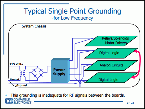
Grounding Demystified – Seminar of Compatible Electronics, Inc
In Other ADCs the analog ground and digital ground may be shown shorted in circuit.
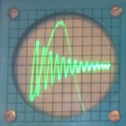
The digital ground carries the power current to digital circuits in the chip. This current will have pulses due to switching of many digital outputs. The short, wire or link shown is circuit is assumed to be ideal in design. In fact the short, wire or PCB track has resistance, capacitance and inductance. These small values of RLC in a PCB track can cause strange AF-RF behavior.
Staying Well Grounded Analog Devices
Successful PCB Grounding with Mixed-Signal Chips Maxim Integrated
The ideal is the digital ground should be a track going directly to supply ground. The analog ground should be a track linking to the measurement circuits or sensors. The analog and digital ground now should be linked close to chip. This link will carry no current, so no ground loop, so no lifting of ground.
This ground problem can reset microcontrollers or timers when a solenoid or relay operates. Similar problem produces hum, feedback oscillations in Audio systems.
Radiating grounds, ground planes, thick tracks, decoupling caps can be remedies. see this link too.


