
ICL7135 PCB Layout Method
I have design a PCB layout for a 4.5 digit voltmeter using the ICL7135 chip, and i have problems with the analog and digital ground. Do you know if somebody have make a PCB for this chip?
I have seen in your schematic a superb circuit- del2003.sch, ICL7135 based auto ranging DVM. Do you know if the PCB layout is avalaible?
I will appreciate to have some help or if someone can send me the PCB layout for the del2003.sch.
Thanking you in advance,
Mail from RL
I am not able to locate my PCB Layouts, but to study about analog and digital grounds for this chip and pcb layout see this Service Manual i found online.
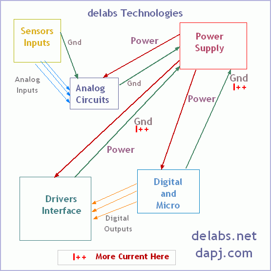
Digital Grounds have Switching Noise or Pulses, Interface Grounds have higher currents. Sensor Low inputs that are not isolated may have potentials and may lift the system ground and also pose hazard. Electrical Earthing and System Grounding are also different things.
Keep the analog and digital current return paths separated. Remember all tracks and wires are resistors and conductors too. connectors have contact resistance. soldered joints (and connectors) have thermometric EMF. Looping Tracks is wrong Radiating tracks is right.
Read this PDF too Grounding in mixed-signal systems demystified, Part 1
Undoubtedly, grounding is one of the most discussed subjects in system design. Though the basic concepts are relatively simple, the implementation is difficult. For linear systems, the ground is the reference against which the signal is based; and, unfortunately,


