
Millivolt Source for Calibration
I was looking for a simple MILLIVOLT SOURCE for ion electrode testing and came across your pdf schematic. This design would appear to fit my needs perfectly, but I have a couple minor questions that I hope you could provide answers for:
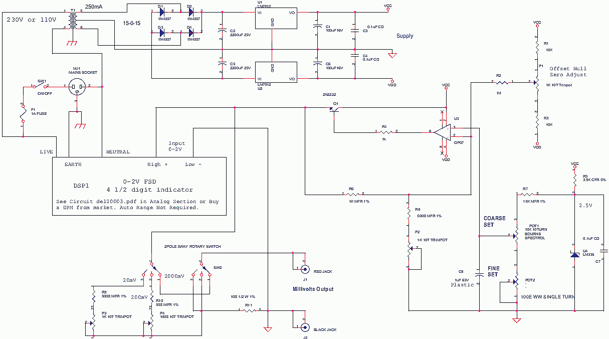
The pdf drawing (Document Number ST02) is not clear with respect to the U4 op amp circuit, namely the connection of components R9, P4, and R10 to the op amp. I assume they connect to U4 pin 1 and pin 8 respectively as a balance or offset feature — maybe you can confirm this.
Also, it is not shown where the terminals of the potentiometer P4 connect to — do they go to Vcc and Vdd? And where does the slider 2 connect?
There is no problem with the rest of the circuit being readable. I expect capacitor C7 would have to be a low leakage type.
NPN transistor Q1 is shown as a BELL100, which I could not find in my catalogues. Could you suggest a suitable replacement?
Thank you for taking the time to check these points. Your answers will help in bread boarding this instrument
mail from AS
R9, P4 and R10 are for balance and offset as you said you can use it that way, but see the new circuit.
Millivolt Source In this link see at bottom this circuit millivolt source, pdf.
I have put a better offset null, OP07 has around 75uV offset error which may show as +/- 1 count error on 4 1/2 DPM 19999 counts. You can skip it if you are using a 3 1/2 digit DPM as the error will not show, even it 4 1/2 it may be upto 2 counts only.
C7 can be a low leakage plastic cap, even a tantalum electrolytic is ok, aluminum electrolytic may cause a very small error.
Q1 can be any npn that can take 100mA current, do not use RF devices, 2N2222 is best.
If you use a DPM protect DPM inputs with clamping diodes or zeners or an error in bread-boarding may send +/- 12V to DPM and it may be damaged. Some DPMs come with protection like DMMs. use the circuit in del2003.pdf in analog section to make a 4 1/2 DPM.
Also in 2000mV range do not short outputs as the Q1 may get damaged, and in 200mV and 20mV range the output impedance is 10 ohms which is good for calibrating any high input impedance instrumentation like a process indicator etc. loading with 100K 10K will cause error.
Most instruments are very high impedance so it is fine.
delabs


