
Logic Analyzer on Computer
Title: Test circuit for Logic Analyzer – Message: I am a retired hobbyist. Source files needed.The following was submitted on March 8th, 2008 at 06:47AM (CST). Subject: delabs Schematic Source Request. Circuit: del20006.pdf .
Mail from JL USA
Sorry for the late reply, Can you explain in detail your doubt or problem. Meanwhile Have a look at
these circuits
40MHz 32 Channel Logic Analyser It is a 32 Channel, 40Mhz, fully PC controlled TTL/CMOS logic analyser with internal/external triggering and trigger delay. Internal triggering is fully maskable (High/Low/Don’t Care) on all 32 channels.
FPGA Based Logic Analyzer The project includes the actual analyzer in VHDL (for Spartan 3 FPGA) and a PC Software for the end user. The design employs a FPGA board that can be obtained easily.
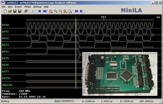
MiniLA – logic analyzer SW & HW.
MiniLA is a project of simple and cheap logic analyzer designed for amateur and semi-professional work.
delabs
I am interested in obtaining a copy of the file “Logic.zip” referred to in the article. PC-Based Logic Analyzer (below). The link to the file is not available. The file contains the software for the circuit described.
Reply from JL


