Battery Management and Supply Design

As you have have pointed out, my circuit is not driving any motor or such loads…but it is driving a Wireless Module which draws about 165mA to 240mA from my circuit during transmission [for 4 sec] and normally it takes upto 114mA. After a time-out of 1min, I put my uC P89V51RD2 to powerdown mode [200uA in this state].
Read articles in the link you provided, thanks for that! – Continued from uC Board is Misbehaving on Brown Out.
My other problem is that my batteries get supercharged upto 5.8V, and as per spec’s of most IC’ they are bound to operate faithfully upto 5.25[max 5.5v], so how do I solve this issue? I want that my boards get only 5.25v even if my battery is having voltages 5.25+, without increasing my existing current consumption to noticeable value.

Moreover I’m in need of a cutt-off circuit which will take away the load from my batteries when my battery has reached 4.00V, & the charger charges my battery independently. Do you have any thing which will suite my purpose?
Mail from MO
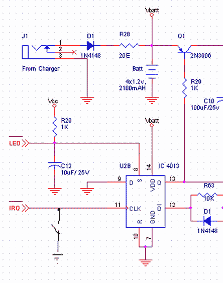
Have two supplies, the one for uC can be a small Ni-Cad battery charged by a diode by the bigger battery which supplies the 200mA for RF drivers.
So when the big battery is loaded and the supply dips the shock is not felt by uC. or isolate it by SMPS and isolate the grounds. The ground return current of RF module 200mA must be lifting the ground of uC or some Logic.
Start by trying to locate the problem, first power RF and uC boards with isolated lines from two lab-test 10A power supplies. If both are in same board, cut tracks and power them separately. The grounds should meet at point the two sections interface.
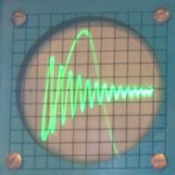
If that works without problem, you know it is related to supply, now step-by-step go back to the battery and charger you have built keeping isolation intact. Look for spikes-glitches on power lines of uF when RF module active. Check if that is close to or leaking RF to uC circuits.
The battery charger circuit should limit voltage and current to battery specs. If you are not using a charger chip then while testing make sure the charger has a regulator or use LM317 to clamp voltage to 5.6 or 5.5 as per your design.
There are charger chips from maxim, national for battery charge management. If you have a need for extra voltage the you have to use SMPS boost switcher. which may take the low battery 4 to 8 which can be regulated to 5 using 7805.
This may be getting bit complex, first try to find what is the problem, it may be just the board design.

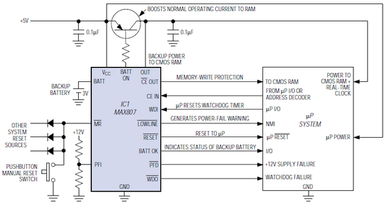
You can also use a Single Maxim Chip for all these functions. …
Supervisor ICs Monitor Battery-Powered Equipment
A feature-laden µP supervisor (IC1), with the help of the µP itself, performs a variety of functions in this typical application circuit. You can get these functions all together or in various combinations, by selecting one of the many available microprocessor (µP) supervisor IC….
delabs


