
RS Latch Erroneously setting by Itself
I am having trouble preventing my rs latch from erroneously setting. The circuit is a voltage threshold detection circuit with a nand gate whose output is tied to a SR latch.
I have capacitors across the VDC and ground for the chips and I verified the power supply’s input is fairly stable. As further troubleshooting I probed with a oscilloscope at the SR latch’s input and looked for anything above 1 V. The voltage never moved above 1V, but the latch still set.
I was able to place a .3 uF capacitor from the SR latch’s input to ground and this seemed to fix the problem. However, it does not explain what is causing the latch to set. Any ideas or suggestions would be much appreciated. Thanks.
Some info:
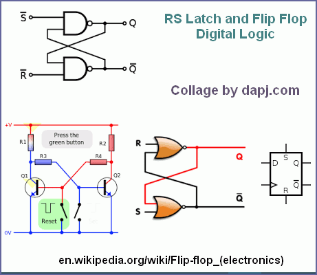
Nand gate: SN74LS30
SR Latch: CD4043B
Supply to ic’s is 5V from a LM7805 (with .1uF cap’s across input/output)
Voltage threshold detection coming from LM339 comparator
Basic idea:
Vin ———-> |LM339 pin 4| -> -> |(relay driver circuit)||nand gate| -> |SR latch|
Vthreshold -> |LM339 pin 5|
Mail from SM
If the power supply is stable and you do not have ground loops then that is not the problem.
If a relay or LED or some output is being driven, the current pulse may be triggering the circuit. Isolate Grounds of Loads even LEDs and Relays, Ensure EMI-RFI immunity.
Use a 400MHz Scope and set timebase to uS-nS and see if a Spike is causing the trigger. Set the brightness level a bit high and look as close as you can.
Even a IC consuming a little extra power for a mS can set up a spike in the rail. Keep power and signal circuits on different PCBs when designing.
Check the environment and mains wiring, It could be a Laser Printer sharing the mains. If a Loose contact is present in mains box then your test circuit links with printer. Finally a good earth or ground is a must, if the unit is to operate on mains.
In the LM339 comparator use a Hysteresis Resistor feedback of 10M or 1M, Also a small cap can be placed across 10M, like 10nF if the system is a slow response one. Ensure you do not put a cap in a way to cause oscillations. A RC at input of LM339 may help.
Finally a LM339 output may have to go thru a schmitt nand buffer like 4093. to Clean the signal. Interface from a LM339 may be good with CMOS and not TTL, so a Scmitt can be tried. Nand gate: SN74LS30 and SR Latch: CD4043B seem to be different families. Use the 74HCT30 and 74HCT4043, use any one single family in Logic.
delabs
One thing i left out, The power on Start of the circuits must be defined. So a power on Set or Reset Cap with a pullup has to be provided if it is triggered by a Low. If you use a Latch which triggers by a Positive Edge then A pull down R and a Pull up Cap is required. – delabs


