
AD590 based Temperature Sensor
Learn how to use the AD590 to measure environment temperatures for display, logging or cold junction compensation.
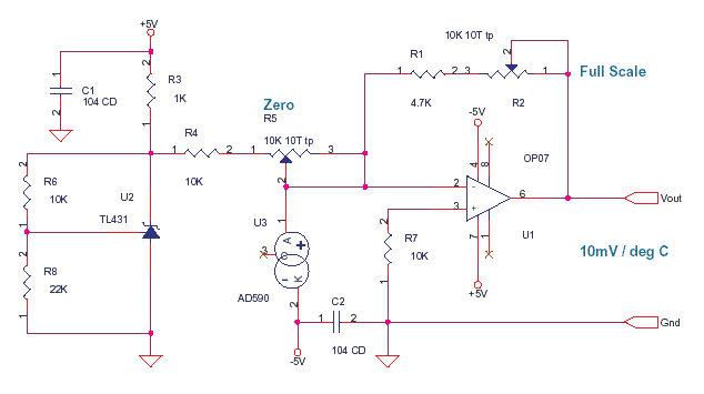
The voltage at the point 1 of R4 will be :Vo=( 1+ ( 10K/22K)) * Vref = 3.63V as nominal Vref is
2.5V.AD590 is a current source which gives 1 uA / kelvin, It is independent of the voltage across the device. you can treat it like a current source or sink or impedance. total voltage across AD590 is 5V as opamp pin 2 is at virtual ground.
Analog Circuits – OpAmp, Signal Condition, Mixed Signal.

This is the way you try to understand the design.
The AD590, here is a constant current sink as cathode goes to -5. The current it sucks away or drains from node pin 2 of OP07 is 1uA/ kelvin. at 0 deg C the current drained is 273 uA at 26 deg C it is 300uA.
You know according to theory that the amount of current entering the node, is equal to the amount of current leaving the node. do not look at voltages now, look at the currents. the AD590 drinks 273uA from Node pin 2 of OP07 at 0 deg C. Now no current can come from opamp OP07 pin 2 as resistance is in giga ohms and leakage in pico amps. now the pot R5 and resistor R4 are just in series and connected to 3.63 V as established earlier. The TL431 is a shunt regulator with reference and has a low impedence. Now the R5 + R4 combination should not load the TL431, that is not the case as 3.6 / 10K = 360uA .
By varying R5 pot you can pump 3.6 / 10K = 360uA down to 130uA when R5 is max into node pin 2 of OP07. This pot will be calibrated with AD590 in ICE to give a 0 mV output of the Op07. When calibrated R5+R4 pump 273 uA into node pin 2 of op07. this is sucked away by the AD590 which is draining 273uA at 0 deg C. This leaves the pin 2 at zero potential as currents leaving = currents entering.
Now to understand the opamp functioning.
The pin 2 of opamp is a 0 potential as calculated above and pin 3 also is at zero pulled down by R7. Now as both inputs are at same potential the output of opamp also is zero. The feedback resistors R1 and R2 will carry no current as both their ends are at 0. the Vout is now 0 mV and AD590 is on a block of ICE and opamp is stable.
If pin 2 (-) becomes more dominant or positive than pin 3 (+) the output swings negative. If pin 3 (+) becomes more dominant or positive than pin 2 (-) the output swings positive. The opamp on feedback tries to maintain both the inputs at the same potential. This thumb rule can be used to make opamp oscillate, amplify or compute.
Now what happens when the AD590 is removed from the block of ICE. It comes to room temperature say 26 deg C which means 300uA. Now the AD590 demands to draw 300uA from node pin 2 of OP07. The R4 + R5 from 3.6 V can give 273uA as it is fixed, not a uA more. The rest which is 300 – 273 = 27uA leads to a drop in potential at pin 2 and it turns negative. as demand is greater than supply. which makes pin 3 which is at zero more positive than pin 2. ( theory : 0 is positive compared to -1) as pin 3 is more dominant opamp swings positive as per thumb rule. and a current starts flowing thru R1 + R2 till the current reaches 27uA. at this point the extra current 27uA drawn by AD590 is supplied by opamp thru R1+R2. The Pin 2 now comes to 0 as currents leaving = currents entering.
Test & Measurement, Instrumentation
At this point the voltage at opamp output is given by ( R1 + R2 ) * 27uA = 270mV (assume R1+R2 is 10K after calibration) now opamp gives 10mV per deg C.as opamp now is a closed loop control the rise and fall in temperature, results in AD590 current variation which produces a proportional OP07 output.
Now the explanation above is in steps but all that happens in real time in an instant.