
Using Thermocouple with DMM or DVM
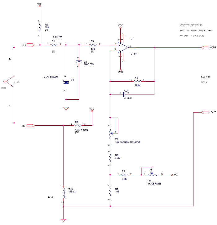
In the circuit, use only metal film resistors (MFR) of 1 per cent tolerance, as this is an instrumentation application. Power supply should be a stable +5V, -5V supply, for which one can use 7805 and 7905 regulators.
The inputs TC+ and TC- terminals should go to a 4-way barrier terminal block, the 2 extra terminals are used to mount TH1 Cu thermistor. This forms an isothermal block, which is good enough.
A simple way to make a TH1 Cu thermistor, is to take a 1 Meg-ohm 2W resistor as a former and wind 2 meters of 46 SWG enameled copper (Cu) wire (5.91 ohm/meter) over it. This gives a 12-ohm value. Terminate wire ends on resistor leads.
Thermocouple Temperature using DPM or DMM
Test and Calibration –
For calibration, you will need a DMM-DPM and a milli-volt source (as shown in the Fig.). First connect source to terminals TC+ and TC-, then set source to 0.00 mV (verify with DMM for zero). The output across +out and -out (use DMM) terminals must be mV representing the room temperature (RT). For example, if RT is 30° C (use a glass thermometer) then +out should be 30mV at 0mV input. Adjust VR1 till 30mV is read at +out terminal. This is ‘zero cal’.


