
The Return of Bright LED
From my Thunderbird archives. it may be interesting to read, maybe you may learn a thing or two.
Many thanks for your quick reply – much appreciated. The FET solution is new to me, but I have tried most of the others.
I think the problems are:
1) As voltage for these LEDs drops from 4.65v, fairly quickly, the constant current starts to move.
2) The ‘constant’ I can acheive would be only 4% while the current is stable.
Do you think my problem can be solved? Many thanks again,
Mail from AB 2006
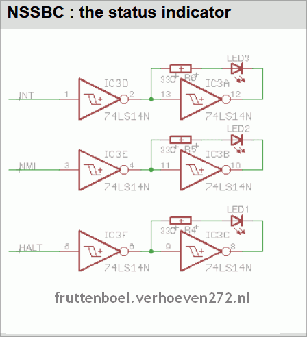
On the right we see the status indicator drivers. One 74HC14 gate buffers (and inverts) the signal. The other gate re-inverts the signal. The trick now, is to mount the LED and resistor in parallel to the second buffer gate.
The example above may be the solution you need…
The LED you use needs 20mA at say 3.3V as per datasheet you sent. 3 AA batteries are 4.5V right, and say 20% drop is 3.8V ok.
Of the 3.8V 3.3 is needed by LED we have only 3.8-3.3=0.5 left With 0.5V dropped across Control Transistor PNP, you have nothing left.
A simple idea is to use a cmos chip 74HC14 to drive LED. Instead of constant current you flash LED at High speed. This way Battery and LED will last longer and work at lower voltage.
The LED flasher circuits below operate on a single 1.5 volt battery. The circuit on the upper right uses the popular LM3909 LED flasher IC and requires only a timing capacitor and LED.
This 1.5 volt led fasher runs more than a year on a single ‘d” cell and alternately flashes 2 LEDs at about a 1 second rate. The circuit employs a 74HC14 CMOS hex inverter that will operate at very low voltages (less than 1 volt).
delabs – 2006


