
Motor driver H-Bridge partial
I envision a design based on the ST TD340 (page 19 of attached spec.) utilizing the power MOSFET IRF3709S (attached spec.) with external PWM-Signal (provided), separate external controller supply 20-30VDC (provided) power supply for H-Bridge up 20VDC 50A (provided) with screw-terminal type connections for control and power enclosed in a (preferably) DIN-Rail mountable enclosure that would be housed in a control cabinet (dry, 30-40C)
TM USA
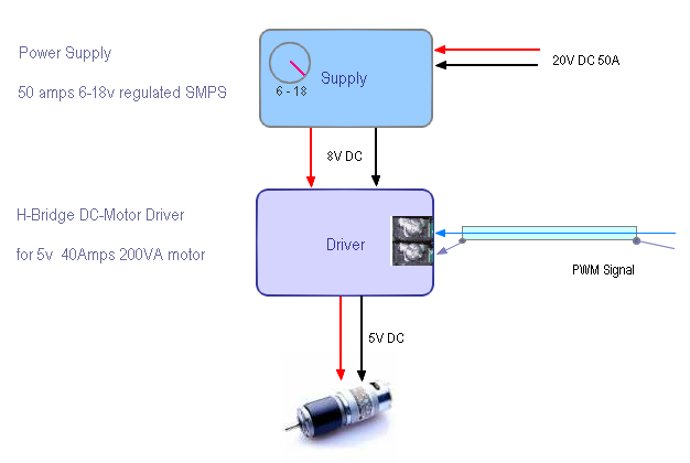
This part below means that you have a 20V-50A DC supply which will power this system ?

“50 amp power supply with 6-18v regulator in a Board size 72mmX120mm” separate external controller supply 20-30VDC power supply for H-Bridge up 20VDC 50A
First Circuit – regulator circuit with 6-18V Variation.
Second Circuit – see attached clip from the datasheet H-Bridge Motor driver.

The two terminals are for PWM DC control signal or potentiometer for Driver. That means you are not using a Microcontroller, PC or Digital control.
delabs
The application is to test DC motor based module. We will be controlling the speed, using PWM. Now we are looking for just an H-bridge driver using the components, we specified.
Addtional information, I can add onto is
1. Two screw type terminal for PWM signal
2. 50 amp power supply with 6-18v regulator Baord size 72mmX120mm
3. The Max voltage is sent to the motor is 5V.
TM USA


