
Building a mV Milli-Volt Calibrator Source
Hi, I am trying to build this mV source that you have drawn on your site. It requires a 5vdc power source with a 1k resistor in line with a 10K pot. Your schematic shows also with the pot a 10k resistor and a 100E component which I have no idea what that is.
My question to you is… does the 10K pot include the 10K resistor and the 100E component or are they separate from the pot? If they are separate, what is the 100E component?
Thanks, KN USA
Dear KN
I would like to know the Circuit File you were referring, i have many on my site for instruments. Let us understand the Theory so you can build your own.
First – You need a Regulated Power Supply for these circuits to be accurate enough. We do not need things like 0.01% for Industrial Electronics or Field Calibration. You can always keep one of these accurate ones in your Lab.

Second – Now to bring down the Voltage of say 5V to mV, we need to Attenuate right. An attenuator contains Two Resistors. The High Value – like 1K is a Fixed MFR 1% Resistor. This faces the 5V and Then comes a Multiturn Pot, preferably Bourns or Spectrol 10 turn, This is 10K. These two form just the One part of the attenuator.
See another design here Current Source mA for calibration
Third – This is a 50 ohm or 100 ohm shunt made of 1/2W MFR 1% or Resistors in parallel to get the value. The reason being that the shunt should not even warm up. The 1K resistor is to protect the pot when wiper is at the 0 ohms end and the shunt is shorted by some mistake. If all these can be built in a box with a fixed temperature using an artificial oven. AND. If you make the Regulated Supply using Opamps and a Precision Reference. You have Laboratory grade Instrument, almost.
This is the site location that I am referring to. The 100E is confusing me.

Thanks
In this Circuit, The 100 ohms is very important as it acts like a Low Impedance Voltage Source. In Fluke Sources 50 Ohms is standard. The Voltage across this resistor is in millivolts due to the attenuation.
10K/100 ohms is 10,000 ohms divided by 100 ohms. That gives a Divide by 100
5 Volts divided in 100 parts Gives 50 mV (approx as we have the bourns 10 turn pot before the 10K/100 ohms divider. )
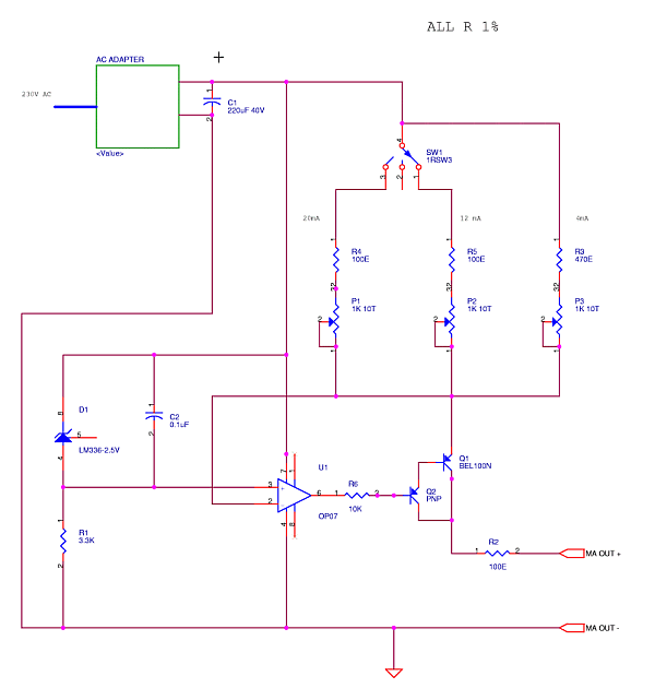
This is easy to rig millivolt source for field calibration or troubleshooting of 4-20 mA current loops. Here a Darlington pair is used for current amplification which reduces the Ib error as gain is very high.
A rotary switch selects, 4-12-20 mA Preset points. A Bourns multi-turn wirewound Pot can also be used with a digital dial. Enclose in a dust proof handheld box. Read more on process calibration.
You can also use one of the Arduino Analog Outputs and Attenuate them after filtering with a cap. This creates a Programmable Millivolt Source.
So, the 100E is just a 100 ohm resistor aside from the 10K pot? What does the “E” stand for?
E means Ohms. Philips used this notation first as the Symbol Ohm was difficult to Print.
100 Ohm Resistor is important, when you connect it to a Device to Calibrate it will not load it. A DMM has a 10 Meg Ohm Measurement Load. The Instrument you calibrate must have around 1 Meg or more. That is why we use FET input Opamps to measure the mV of Thermocouples.
That is where the millivolt source steps in, it is a Thermocouple Simulator.
thank you very much
KN


