
Digital Interface Part Two
Continuation of Digital Interface Discussion, only my part of the communication here. This will help you understand some common methods and issues.
Use a IO port to drive low (not pulse) the base of this PNP with a resistor 10K, emitter is +V and collector is the output to power the Sensor V+. You can use a pull up resistor on the port like 47K to keep noise low.
InfraRed LED Flasher for Optical Switch
Try things practically before you connect to the Embedded System. Make test codes to check your interface circuits, watch the LEDs flash on off on the sensor. Test the sensor with obstacle and see if a clean High Low pulse is seen with a scope or DMM on a Port input.
There has to be a 100 uF 16V Electrolytic Cap in the Breadboard across +/- (supply terminals) coming from Battery. This is the first decoupling cap to prevent oscillations. It acts as a mini battery. It should be on the board and not soldered across the battery.
Optical Retro-Reflective Proximity Switch
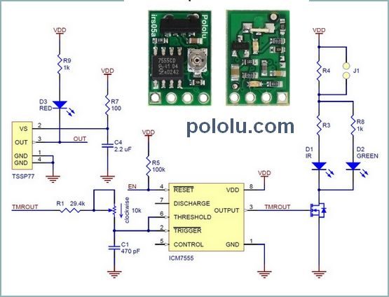
It may be a good idea to use this pololu sensor which can be easily enabled and disabled. This will resolve most of the issues of interfacing basic IR circuits. This post is about other raw IR sensors which need more circuit to interface well.
Pololu 38 kHz IR Proximity Sensor, Fixed Gain, High Brightness
Yo may need a bleeder resistor 10K across the supply terminals of both the proximity switches. This ensures the cap in the proximity switch discharges after you turn off the supply within a few mS determined by the 104 decoupling cap in the proximity switch and the bleeder a 10K will do.
Use a dedicated port, not used for anything else. Ensure output is steady or latched, High or Low all the time. Multipurpose ports output need to be latched externally when used for more than one function. They will be pulsing.
You will need a 100K pullup near the Input Ports which gets the low signal from the sensors, this is to ensure input does not float and is noise immune.
If the low happens for a very short duration like micro seconds (like trigger pulse or fast moving object) you need to detect it fast in software or use Scmitt triggers or monostables to expand width of pulse. This can be found by practical experiments.
It is better not to wire OR the proximity switches, OR it in Software, use two input ports. Grounds should radiate and not loop. circuit shows a ground loop but breadboard is correct.
PNP conducts when a Low thru a resistor is applied at base. If Emitter is at 3.7V the base should atleast go to 3.0V to have some conduction. We take base to 0V thru resistor, PNP turns on, the power goes to Collector and Activates the dead Optical Switches. When PNP is not turned on, the base should be pulled up, hence the Resistor 100K to V+. The Port also can be High or Float. But when port goes low, PNP turns ON and the Optical Sensors start working..
After wiring this, make a test code just to turn on and off The PNP for 30 Seconds. 10 Sec OFF 30 Sec ON. Then you can see with DMM.
Even after circuit is correct, bad connections, bad or wrong parts and improper testing may cause adequate confusion. That is what makes EE Interesting.
If you use Thick MultiStrand Copper wire and make proper connections it may be ok. It is better to have the GND of these devices come directly to Battery GND Node on a terminal, When these devices turn on the current may lift up the GND if wires are thin or due to Loose connections. Wire resistance and contact resistance too. This may lead to noise, Unexpected Resets to Board or wrong LOGIC level interpretations.
So a robust and reliable design should foresee all problems.