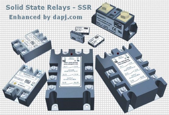
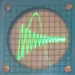
SSR Open Circuit Leakage Voltage

hi been trying to use a dc ssr relay to switch 24 volt supply on and off for a unit i use that needs to see 0v or 24v but when the switch voltage is applied there is still 18v showing on the load side not zero ..does the ssr have to have a load on it to fully switch off and on from 0v to 24v ?
Mail from PST in UK
You are right you need a bleeder resistor of 10k or 100k to ensure the collector leakage current of SSR is bypassed to make you see a ‘0’ when the SSR is off. If the SSR is working well, and no input or ‘0’ control input then SSR output is high impedance and only a collector or diode leakage will hold the SSR output at the Full Voltage but it cannot drive any current. Hence a bleeder across output will show you a ‘0’. Use it if the bleeder does not cause any problems.

If you were driving a 5A Solenoid, then you would not see this problem. If you are driving a Solid State Load, such effects are natural. It is because the Solid State Load like a Electronic Circuit will draw current only on demand.
These instruction is for a Normally Open Output, NO. A Normally Closed NC is vice versa. And also some Special SSRs may have sensitive inputs, So a low impedance ‘0v’ at input has to be ensured.
The Bleeder should bypass the leakage current, so one end of bleeder goes to SSR output and other end of bleeder goes to the ground or 0V point of your circuit which is controlled by SSR.
delabs
They are called SSR as there are made of semiconductors and have no moving parts to wear out. They do generate heat depending on load and switching. Thyristors are used in most as they are rugged, mosfets and IGBT may also be used for various applications.
In this section you will find SSR designs and PCB layouts which you can study. These were made and sold by me years ago. So the PCB layouts have gone thru some revisions and they worked quite well.


