
Mixed Signal Grounding Method
How do we interface Analog and Digital Blocks. The earlier post explains ground connections that are radiating from supply but does not show Analog and Digital Blocks Interface.
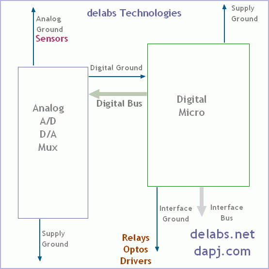
Analog Blocks have Opamps, Analog Mux, A/D Convertors and D/A Convertors. Some microcontrollers have built in A/D and D/A then you have to use the separate ground pins they provide. The implementation remains the same.
The diagram above is self explanatory. There are mainly types of return ground paths… to the power supply ground
Pulsing Ground – From Digital circuits that are switching in MHz speeds.
High Current Ground – From Interface or Power, LED, Motor Circuits.
Clean Signal Ground – From Analog Signal Conditioning and Mixed Signal.
Use proper decoupling caps at every chip and every functional circuit block. Have a ground plane that doubles up as a shield in on or more layers of PCB. In RF circuits you could use two ground planes on two layers of pcb and signal tracks in between.


