LM311 Square Triangle Oscillator for PWM
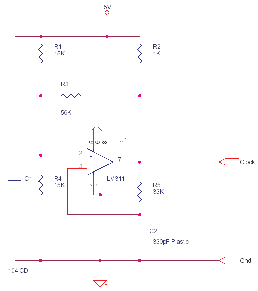
LM311 is a comparator, It operates from single 5V supply or dual supplies,input current 150 nA, 50 V-50 mA output drive capability. TTL-CMOS compatible output.
Even LM324 used as a comparator Water Level Indicator with Reed Relays
The Output is open collector so it can sink current but cannot source, a totem pole output can source and sink. In this Circuit R2 is the source or pull-up.

The Output being high or low depends on which input is more dominant or positive. If + or non-inverting input is more positive than the – inverting input then output of LM311 is high impedance or high Z as output transistor of LM311 is turned off, but output goes high due to R2 pull-up 1K, so you can apply a load of 10K and above for source. When the – input or inverting input is more positive, output goes Low as transistor turns on, now a current of upto 50mA can sink here, a LED or Relay can be driven.
Mixed Circuits Analog with Digital
On turn on C2 capacitor is discharged and pin 3 the inverting input is at a lower potential than pin 2 the non-inverting which is at 2.5V. Hence output goes high and C2 starts charging thru R5, When C2 charges a little beyond 2.5V pin 3 is more dominant and output goes low now, this slowly discharges the C2 bringing the voltage at pin 3 again below 2.5V so output goes high again. This process goes on, hence it oscillates. The charging and discharging is at the rate of R5 * C2 approx. , R3 serves as hysteresis or feedback to ensure clean turn on and off.