
Insulation Tester power supply
With these circuits you can make an insulation tester going upto one tera ohm (2 Tera ohm max). hence currents will be in pico amps, great care required in design. Also 1000 Volts DC is generated which can cause injury. take great care. the above circuit is for the advanced instrumentation hobbyist only, do not try it at home.
Insulation Tester or Teraohm Meter with Polarization Index
The parts list which is not in the circuit is listed below, the circuit is 15 years old. but you may get some idea on high resistance measurement.

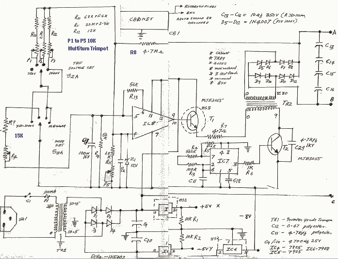
IC7, IC9 – NE555 – Timer IC -o- IC8 – LM723 – Voltage Regulator
The above list is from my memory, hence it may be wrong, i have forgotten this circuit, this circuit was scanned by a hp photosmart and resized and optimized by irfanview. also note the technology may be obsolete, but basic idea is still the same today.
Theory of Operation.
IC7 555 as an Astable chops the DC with T2 NPN transistor. TR2 was a Russian U Core High-Freq Transformer. The secondary was insulated with mylar, layer to layer and impregnated in Mica-Lacquer or varnish. The 723 Chip along with T1 is The closed loop regulator which changes the DC which is chopped.
- Insulation Tester pico amplifier.
- Insulation Tester power supply.
- Insulation Tester Theory.
- Catalog of Insulation Tester.
The high voltage is attenuated and that is the feedback to 723 chip which by comparing to a reference, controls the output. The diodes and caps are in series to withstand 1000V and above.


