
Flashing Mains Neon Lamp
Here is a Neon Flasher circuit (untested) for a user request at Circuits FAQ. This can be built into a switchboard or a gadget for indicating Live Power.
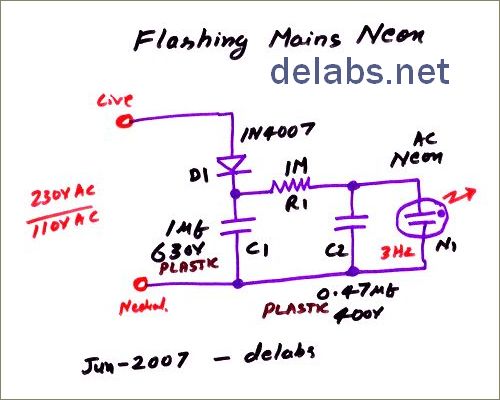
D1-C1 form a simple half-wave rectifier, The Cap charges to peak voltage and can store charge for a long time if there is no bleeder. So while building it take extra care. This forms a DC supply across C1. C1 is a Plastic High-voltage cap, IN4007 has a 1KV rating, so it is ok for 230V rectifier.
See more of my Home Made Circuits.
R1 Charges C2 and when C2 reaches 60-80V depending on Neon, the neon breaksdown. C2 Discharges, Neon Recovers, The C2 starts charging again and so on and on. It Oscillates, probably in a Ramp Waveform. But do not use your Scope on this, you will regret it a lot. This is a live circuit and needs a special probe.
“Oh, i will put the probe it in 10M mode” will not do. The ground clip of the probe goes to Electrical Earth which is ‘connected’ to Neutral in the mains wiring. So you put the earth crocodile clip on the live point. There will be flashes and fireworks. So you need to isolate both terminals of scope. Please use your costly equipment with great care.
For the 1 Meg use two 470K in Series for 230V AC, that is safer. The circuit is live, so take precautions. The 0.47 Micro Farad can be increased if you want a slow flash. If the Mains 50/60 Hz Flicker is too much, the 1 uF can be made 2 uF, or use 4 – 1N4007 as a bridge rectifier.
User Feedback –
R1 of 4.7M and C2 of 0.47uF Works well at 230V AC. Try your own Combination. Less than 1M may damage Neon.


