Temperature Controller Applications
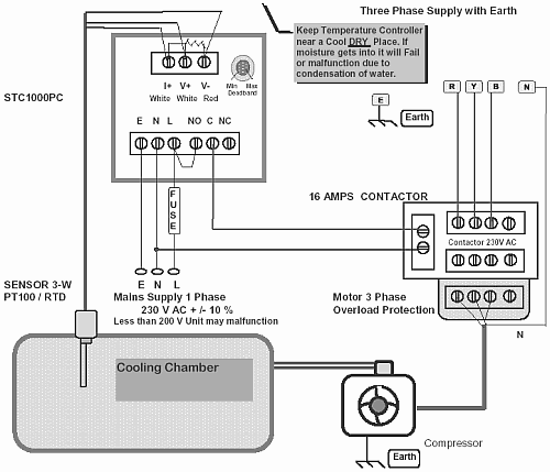
Cooling Chamber Temperature Control
The Logic of cooling in temperature control is inverted, Activating the relay powers a compressor which cools the system. A small modification at the output stage, makes any heating controller into a cooling controller.It can also be done with external relay logic, but make sure on power failure (control power line) the compressor ( 3 ph power) shuts down. In all heating and cooling control, when a broken or disconnected sensor is detected, the controller should turn off all outputs and indicate a fault condition.
Before you use a Controller to Cool a Chamber to Say +5 Deg C.....
The basics of control system design
First :
Do not Connect the Controller. Directly Connect the Cooling
Device e. g. : Compressor. to the system and check the maximum
cooling it can produce. In case temperature goes to 0 deg or
-10 deg then by using a STC1000 you can control at +5 deg.
But if directly you get cooling of only upto +10 deg then it is impossible for any controller to produce extra cooling, in such a case as this use a better compressor or more insulation.
Second :
Connect Sensor properly and replace when broken keep sensor
close to the source of cooling.

Third :
Deadband (DB) at minimum is 1 Deg this is the best setting,
maximum setting of deadband may increase compressor life and
also save power but will produce a huge variation in
temperature.
Instrumentation and Automation - 02
Fourth :
If large Variation of temperature is present and you need accurate control Reduce deadband to min.
Unit is factory set db at 1 deg, remove seal tape before dead
band adjustment.
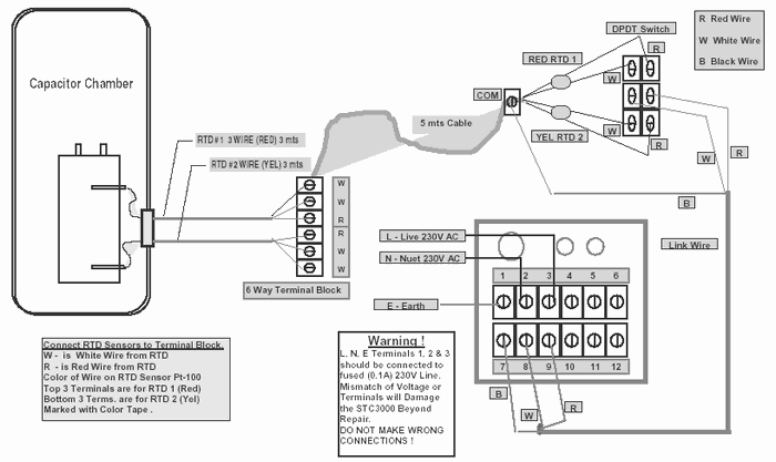
Capacitor Temperature Monitor With STC3000
When placing sensors in high pressure or vacuum chamber, they should be terminated by an epoxy sealed terminal block interface on the system. 4 wire RTD is best for such applications, as multiple terminations and junctions are involved; also the wires may have to run some distance. (hermetically sealed)When measuring temperature in a big surface or object, use multiple sensors. An indicating scanner-controller can be used or ensure cooling-heating is uniform using fluids or air circulation.
Precision Temperature Control with PID and SSR

RTD Sensors to Terminal Block Connections
Top 3 Terminals are for RTD 1 (Red), Bottom 3 Terms. are for RTD 2 (Yel), Marked with Color Tape.
The RTD two whites go to one end of the Platinum 100 ohms resistive sensor, the red goes to other end. The red in this sensor goes to gnd of opamp circuit in controller. Thru one white a 1mA current is injected, the other white gives a voltage output to opamp. This voltage after offset and calibration is proportional to temperature.
Back to Process Control
Applications
...
...
...
...
...
delabs Technologies
30th Aug 2020
...
The documents, software, tools and links are provided to enhance the ability of an electronics student, hobbyist or professional by sharing information. The information, links etc. should be used by the website visitor, at his or her own risk and responsibility. There may be concept, design and link errors in the pages.
Creative Work, ideas and documents of delabs can be used for Product Design and Development by R&D Engineers, Hobbyists, Students and even firms for creating useful products. These cannot be used for reprint, replication or publishing online or offline.

