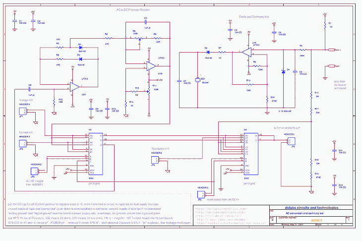
AC conversion and continuity buzzer test - del20012
U1A LF353 opamp turns on a buzzer when the voltage at Test + falls very low indicating a short between Test + and Test - or a resistor less than 5 ohms. The R9-R14 divider determines the minimum voltage that can be at Test + for buzzer to just turn on.The Opamp here is a comparator and R10 10 Meg gives a very small hysteresis so that there is no oscillation at threshold levels, that is when both inputs at same levels.The Zener is for protection and R6 to limit current.
Electrician Tool – Continuity Tester
U2A and U1B opamps form a precision rectifier, note that this is not a true RMS rectifier circuit for that see some devices from Analog Devices. When you need to rectify a 200mV AC signal you cannot use a diode like 1N4148 as the diode turns on at 700mV so this circuit is used.

PNG-Schematic PDF-Circuit DSN-Source
AC conversion and continuity buzzer test - del20012
To view circuit. Click the Link of PNG or PDF and view the Circuit, PNG can be Scrolled with Mouse.
The AC signal measurement is best to do with a True RMS convertor. This Type is able to quantify the Heating power of a AC voltage, includes all harmonics and Noise too.
AD636 - True RMS to DC Converter
This circuit above is just a precision rectifier with filter. It assumes a sine wave is being measured and is calibrated for such a measurement. A Triangle, sawtooth or square will give errors.
The Continuity tester is a Voltage comparator that helps electricians see if the Wire or Switch is a Open Circuit or Shorted. The Audible sound helps quick sorting or check, sometimes a Flashing LED will also help
...
...
...
...
...
delabs Technologies
20th Mar 2020
...
Disclaimer and Terms of usage
The documents, software, tools and links are provided to enhance the ability of an electronics student, hobbyist or professional by sharing information. The information, links etc. should be used by the website visitor, at his or her own risk and responsibility. There may be concept, design and link errors in the pages.
Creative Work, ideas and documents of delabs can be used for Product Design and Development by R&D Engineers, Hobbyists, Students and even firms for creating useful products. These cannot be used for reprint, replication or publishing online or offline.

