Proportional Process Controller Specifications
Front Panel Controls
Unlike a On Off temperature controller that works like a Thermostat. A Proportional controller turns on for a duration proportional to the heating required to ramp up the process.Thermostat with digital display for PTC1000
If the set value and process value have a large difference the On period may be 90%. When the process value is close to set value, the on period is like 10%.
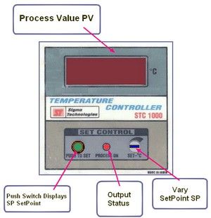
Display - Process Value PV
This is a 3 1/2 digit display which shows the process value from 000 to 1999 as chosen by user it could be deg C, Kg/cm2 or Lts/hr.
Push Switch - Displays Setpoint
This is a push switch which when pressed, makes Display read SetPoint as required by user to control his process.
On-Output Status
LED Indicates Relay ON or OFF in Relay and Pulse Output Units. Units with 0-10V or 4-20mA, Output LED is always OFF.
Vary SetPoint SP
This is an endless 10 Turn Potentiometer this is used to adjust SetPoint (SP) in tandem with Push Switch. Turning Clockwise it Increments SP till max. value, then turn anticlockwise to bring SP to Zero. Use a Plastic Screwdriver or Trimmer.(Tester).
Basic Operation
Press Push Switch to make Display read SetPoint (SP), this is the user defined point at which process is controlled. Now holding Push Switch pressed, adjust SP Pot to change Set Point to required value, use a small screwdriver.
Back Panel Termination
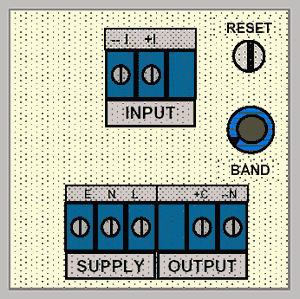
INPUT : 4 to 20 mA, Fused, Polarity is Important. From Sensor, DC Current.
OUTPUT : 4 to 20 mA, Polarity is Important. To Output Device or Actuator, which by using DC Current, drives 0% 4mA, 50% 12mA and 100% 20mA in Linear fashion.
SUPPLY : 230V 50Hz - L, N, E. Connect Proper Earth.
BAND : This is a Single Turn Potentiometer (300 deg) it sets the
Proportional Band of Control. Wide and Narrow are the ends of pot.
RESET : This is a Ten Turn Potentiometer (endless) it sets the
Integral or Reset or Error Cal. Inc. PV and Dec. PV are the two ends of pot.
Electrical Precautions -
- Wrong Connections are the cause of most equipment failure.
- Use Servo stabilizer for extra protection.
- Use a Very good earth connection.
- Use Fuses where appropriate.
- Crimp and Solder all Lugs.
Specifications
OUTPUT :- 4 to 20mA, 4mA 0% & 20mA 100%. < 4mA OFF, > 20mA
ON.
- 4-20mA Maximum Voltage @12V DC ie Shunt 10 Ohms to 500
Ohms.
- Protection - use external fuse of 0.1A to safeguard from high energy circuits.
4 to 20mA, 4mA Displays 0% of Process Value ‘000’ & 20mA Displays 100% of Process Value. This is to be specified by user as ... an example 750 Lts/hr.
Input @ 20 Ohms Shunt in STC1000PFC. Protection - Internal fuse of 2A and Semiconductor Protection Circuits to
safeguard from high energy circuits.
Environmental Limitations :
- Delicate Precision Instrument
- Maximum 50 Deg C, 70% RH Non-Condensing
- Acid-Alkali-Salt Free area.
- Equipment may fail if environment is Hot / Corrosive / Vibrating.
Power Supply : 230V AC 50Hz +/- 10%, Sine wave UPS & DG Sets.
Feedback and Temperature Control
Proportional Temperature Controller
A Temperature controller made with above process controller has the following changes in specs.On-Output Status
LED Indicates SSR ON or OFF. Pulse Output goes High Max 15V or Low 0V. High Pulse turns on SSR. and this is Indicated by LED turning ON.
Display - Process Value PV
This is a 3 1/2 digit display which shows the Temperature value in Deg. Centigrade
Terminations
INPUT : Thermocouple, Polarity is Important.
OUTPUT : DC Pulse Polarity is Important. To SSR. Pulse Maximum Voltage 12V DC at a Load of 250 Ohms.
Read More here - Analog Process Control Circuits
Back to Process Control Instrumentation
...
...
...
...
...
delabs Technologies
30th Aug 2020
...
The documents, software, tools and links are provided to enhance the ability of an electronics student, hobbyist or professional by sharing information. The information, links etc. should be used by the website visitor, at his or her own risk and responsibility. There may be concept, design and link errors in the pages.
Creative Work, ideas and documents of delabs can be used for Product Design and Development by R&D Engineers, Hobbyists, Students and even firms for creating useful products. These cannot be used for reprint, replication or publishing online or offline.


