
Voltmeter Attenuator Rectifier
Measurement of Voltage : – In testing electronic circuits, Measurement of voltages is important for diagnosing faults and making the circuits work. In circuit diagrams given in equipment manuals, voltages at various points in the circuit are usually marked.
Voltage measurement attenuator amp
A deviation from these values indicates that some component has failed and eventually leads to clues for isolating the faulty areas.
Description :-
As our DPM is capable of measuring only 200 mv full scale deflection, the input voltage in the case of exceeding the range needs scaling down. This is achieved by an attenuator chain.
Specifications :-
D.C. Voltage
Ranges : +/- 200 mV, 2V, 20V, 200V, 2000V.
Input impedance: 10 mega ohms.
Circuit protection: + 2000V D.C. all ranges.
Over range: 100% to 1999.
Accuracy: +/- 0.5%.
A.C. Voltage
Note: Average responding Ranges calibrated for sine wave.
Ranges: 200 mV, 2V, 200V, 2000V
Input impedance 10 mega ohms.
Circuit protection : 750V r.m.s., all ranges.
Over range: 100% to 1999.
D.C-voltage -measurement:
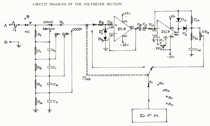
The circuit for the measurement of voltage (AC. and DC) from 0.2V to 2000V is as shown. In case of DC voltage measurement, A mode switch selects the input voltage and passes it via an attenuator chain. Resistors R6, R7, R8, R9 and R 10 comprise the attenuator chain. The attenuation chain is in fact the range selection network.
Build a DMM or Digital Multi Meter
The voltage ranges are provided in 5 decades i.e. 200 mV, 2V, 20V, 200V, and 2000V. The input voltage after attenuation is fed, depending on the range selected by switch Rs, through switch Sad to the DPM input point. The reading on the DPM gives the value of DC voltage being measured.
A.C-voltage measurement:
Most D.C. measurements are made with AC. to DC. converters which produce a DC. proportional to the AC. input being measured and apply this DC. signal to the DPM. Converting the signal to DC at an early stage minimizes the serious errors which otherwise could result from frequency selective circuits.
When an AC voltage is to be measured, the switch Sad is to be operated. This switches enables the signal to pass through a buffer and precision rectifier and then to the DPM input while measuring AC. but passes it directly to the DPM input while measuring DC. So, now the signal after passing via the attenuator chain is fed to IC2. The buffered output of IC2 is fed through the capacitors C 10 and C 1 1 to IC3 (CA 3140-TL071) which is an FET input operational amplifier, acting as a precision rectifier. By means of diode D4 and resistor R24, rectification with gain is obtained for positive half cycles of the AC. signal while the negative half cycles are directly fed back by the diode D3. The half-wave rectified voltage is filtered by the resistor R25 and capacitor C12 combination.
The capacitors C6, C7, C8, C9 connected across resistors in the attenuator chain provide some frequency correction during AC input. The presence of offset voltage in IC3 is to be compensated using variable preset VR2. Preset VR3 is used to correct the reading so as to indicate the true a.c. value of the voltage. On passing the preset VR3, the signal enters the DPM. The reading on the panel gives the value of AC voltage being measured.
Parts List :-
1. Semiconductors
IC2 and IC3-CA3140 or TL071. D1 and D2-5V Zener 1W, D3 and D4-IN4148,
2. Resistors.
a. 1/2 W 1%,
R6-1M, R7-100KE, R8-IOKE, R9-1KE, R10-100E,
R18 and R19-10K, R23-15KE, R24-100 KE, R25-1 KE,
3. Presets.
VR3-220KE
4. Capacitors
C10 and C11 10MFD, C6-47PF, C7-1 KPF, C8-6.8KPF, C9-8KPF, C12-1MFD.
5. Miscellaneous
SSG/T-SOCKET, 51,52-DPDT, A,B,C,D-BNC,SKT, F2-100mA fuse, RS-8P2Wx5 INTERLOCKED. S-2p2wx7 Interlocked