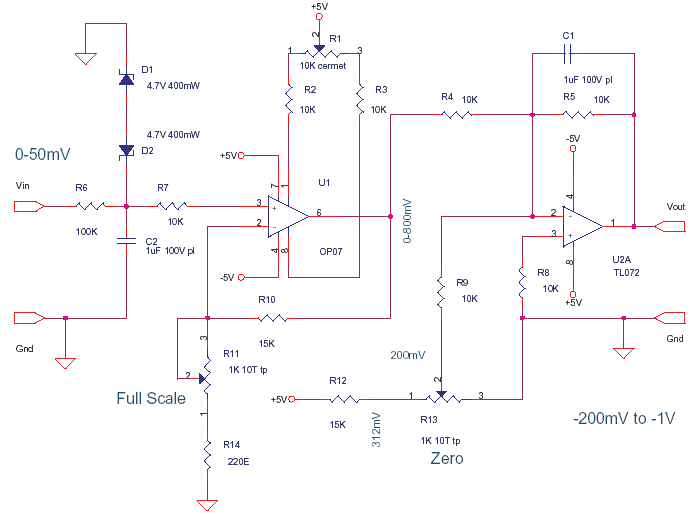
Amplify uV from Sensors to mV levels for A/D Converters, which in turn may drive a display or connect to a uC means MicroController.
I have my own human interface and memory limitation. I am like a 8086 based nobody’s computer in a Penta-Core 5 Ghz Fiber-Computing World, add a 5 Teral Byte HDD. I am Obsolete, i am Legacy.
Now getting back to Bizness, the inputs from the world we interact are analog, A uV level from a Strain Gauge to measure Weight/Pressure; mV from a K Type Temperature Sensor or mV from LVDT Displacement Transducer to Gauge measure linear displacement. All these Low voltage/current, AC/DC need some signal conditioning and special construction – FOR – Amplification, Attenuation, Noise/Pickup Immunity/Rejection, Linearizion, Isolation and Transmission (long wire/wireless).
This means take a small signal sample in the best possible way. The Sensor/Transducer shape and sensing/converting element/technology is chosen/developed. This low mV/uV is then Amplified/Cleaned and Transmitted.Some steps like Linearization can be done by software not all steps. Now we have a nice 0-10 V or 4-20 mA Signal which any A/D with process enthusiastically. The Digital signal will be eagerly processed by a uC with firmware, without batting a eyelid or like the kids say “look no hands” (then its plaster of paris for a few weeks).


