
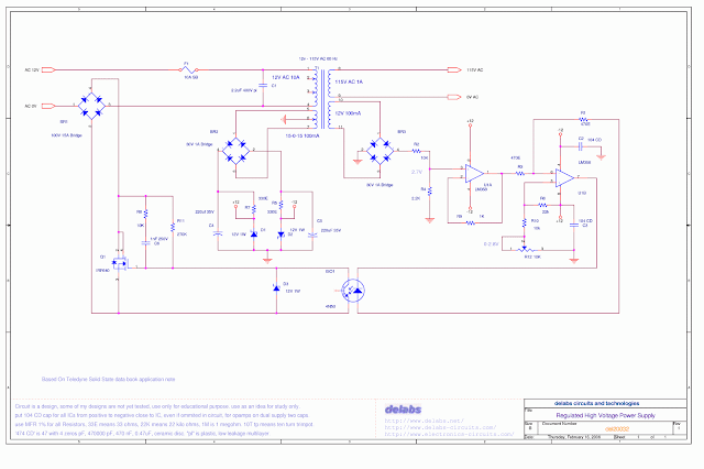
Regulated High Voltage Power Supply
The Circuit below is a paper design and not tested. It can be used for education and information, this can help you make your own design. Please do not just wire it up and expect it to work.

Now let me see if i can explain the circuit, This is a regulated AC power supply. This circuit uses the Mosfet to turn off when voltage goes beyond a reference point. That means it just chops the Sine wave above a point, that also implies that the output may not be pure sine and may have harmonics. The Transformer if well designed may smoothen the chops. Even a Series Inductor or Resonant Circuits may reduce harmonics.
The opto coupler 4N50 Provides isolation and good Current Transfer Ratio. That may mean you may not get a shock and that even a small current signal in Opto-LED will give a saturated or Low Impedance in Opto-Transistor. The Mosfet is used like a Impedance Control switch turned On-Off by Opto. The Optocoupler diode is controlled by the Opamps which work Closed loop. The transformer output is compared with reference to drive opto-led.
Regulated High Voltage Power Supply – del20032
This Circuit is based on Teledyne Solid State data book application note. They may not be making these parts anymore but they are available from others.