
Inverting Amplifier – Op-Amp Circuits
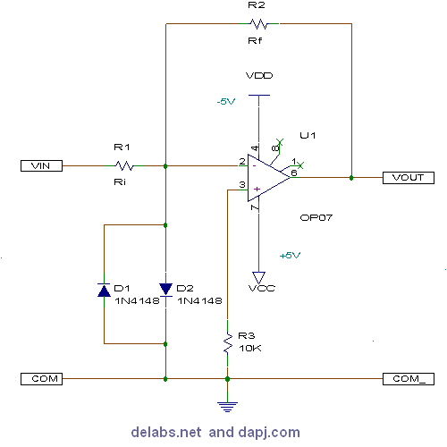
Input Impedance of this module is Ri as pin 2 is at virtual ground, the opamp with feedback tries to maintain pin 2 and 3 at same potential pin 3 is at 0V hence pin 2 is at virtual ground. Clamping diodes protect OpAmp, Rf + Ri is between 5kE and 1ME as an opamp may be able to drive around say 5mA max.
Inverting Amplifier – Op-Amp Circuits
Current into node pin 2 = Vin/Ri if Vin is +ve it raises potential at pin 2, in order to bring it to 0V the OpAmp sucks away the current by turning its output negative the current leaving pin 2 node is also Vin/Ri. Then Vout is given by Vin/Ri * Rf as per V=IR ohms law. Most OpAmps output swings around 1v less than VCC/VDD for full swing use CA3130 this is a FET input OpAmp, and has low bias currents in pico amps.