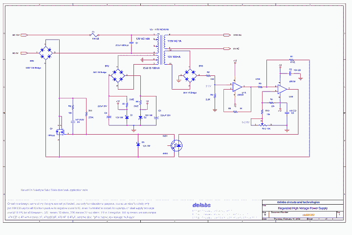
Regulated High Voltage Power Supply - del20032
This is a regulated AC power supply. This circuit uses the Mosfet to turn off when voltage goes beyond a reference point. That means it just chops the Sine wave above a point.It implies that the output may not be pure sine and may have harmonics. The Transformer if well designed may smoothen the chops. Even a Series Inductor or Resonant Circuits may reduce harmonics.Some more types of Mains Voltage Regulation - Mains Voltage Stabilizer Circuits.
This circuit will not work out of the box, i may have made mistakes in documentation. The final working design was not recorded in this schematic. If you are an expert and understand concepts well, try it out.
The opto coupler 4N50 Provides isolation and good Current Transfer Ratio. That may mean you may not get a shock and that even a small current signal in Opto-LED will give a saturated or Low Impedance in Opto-Transistor. The Mosfet is used like a Impedance Control switch turned On-Off by Opto. The Optocoupler diode is controlled by the Opamps which work Closed loop. The transformer output is compared with reference to drive opto-led.

PNG-Schematic PDF-Circuit
Regulated High Voltage Power Supply - del20032
PNG Image Can be Scrolled by Drag-Drop Left-Click-Mouse
This Circuit is based on Teledyne Solid State data book application note. They may not be making these parts anymore but they are available from others.
This concept of control can be even used for Hi-Frequency convertor, but we need to convert to DC before chopping and a PWM Sine Shaper has to be integrated. This circuit could be a replacement for CVT - Constant Voltage Transformer OR Servo Stabilizer. This circuit is more a Solid State Mains Voltage Stabilizer for lower power gadgets.
EMI RFI Filters and Electrical Noise Control
In case you have many 110V AC Equipment but the Mains Supply in your place is 220 V AC, then you could use this both for isolation, protection and regulation. Then you need to modify the design above from a Boost or Step-up Regulator to a Buck or Step-down Regulator. Note that this is a Low Frequency Switcher and even Thyristor Based designs like these existed.
...
...
...
...
...
delabs Technologies
10th Jun 2020
...
Disclaimer and Terms of usage
The documents, software, tools and links are provided to enhance the ability of an electronics student, hobbyist or professional by sharing information. The information, links etc. should be used by the website visitor, at his or her own risk and responsibility. There may be concept, design and link errors in the pages.
Creative Work, ideas and documents of delabs can be used for Product Design and Development by R&D Engineers, Hobbyists, Students and even firms for creating useful products. These cannot be used for reprint, replication or publishing online or offline.

